General
The 10 0G / 20 0G coherent optical module uses a 10 4 - pin CFP2 -MSA electrical connector for connecting the host card.Figure 1-1shows the picture of this module.The optical module consists of three functional parts: TX module, RX module and control module. All the control interface pins are provided by an internal microcontroller. This microcontroller can also be used for modulator control, software management, and alarm / performance event reporting.Figure 1-2shows the block diagram of the 100 G coherent optical module.Features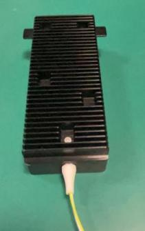
Features
● 100G coherent optical module operating up to 112.30 Gbps
● 200G coherent optical module operating up to 211.45 Gbps
● PM-QPSK (100G)and PM-16QAM (200G) modulation formats
● Electrical interfaces CAU-I4
● CFP MSA Management Interface Specification 2.2 with modifications compliant
● Near-end / remote-end data loopback
● Maximum power consumption: 21 W
Application
The 100G\200G coherent optical module is used on the host system for MAN DWDM applications.
Performance Specifications
1.100G Optical Port
100G Optical Port Performance Specifications
|
Parameter |
Value |
|
Network lane, modulation format |
PM-QPSK |
|
Optical channels |
96 |
|
Grid spacing |
50 GHz |
|
Frequency range |
191.3 to 196.05 THz |
|
Wavelength stability |
±1.5 GHz |
|
Tx output power, default |
-13 dBm |
|
Tx output power accuracy |
±1.5 dBm |
|
Output power during tuning |
< -35 dBm |
|
CD tolerance |
±40 000 ps/nm |
|
DGD tolerance |
33 ps |
|
Input power range |
0 to -18 dBm |
|
OSNR tolerance( typical) |
12 dB (Rx optical power: -8 to -10 dBm) |
|
Power consumption |
Typical: 18 W Maximum: 20 W |
2.200G Optical Port
|
Parameter |
Value |
|
Network lane, modulation format |
PM-16QAM |
|
Optical channels |
96 |
|
Grid spacing |
50 GHz |
|
Frequency range |
191.3 to 196.05 THz |
|
Wavelength stability |
±1.5 GHz |
|
Tx output power, default |
0 dBm |
|
Maximum output optical power |
+5 dBm |
|
Min. Tx output power |
-10 dBm |
|
Tx output power accuracy |
±1.5 dBm |
|
Output power during tuning |
< -35 dBm |
|
CD tolerance |
±10 000 ps/nm |
|
DGD tolerance |
22 ps |
|
Input power range |
0 to -18 dBm |
|
OSNR tolerance(typical) |
19.5 dB (Rx optical power: -8 to -10 dBm) |
|
Power consumption |
Typical: 19 W Maximum:21 W |
Electrical Characteristics
1.Power Supply Requirements
The 100G / 200G CFP2 coherent optical module is powered by an independent 3.3 V power supply on the host. All voltages are tested at the connector interfaces.Table 4-2describes the power supply requirements.
Coherent CFP2 Optical Module Power Supply Specifications
|
Parameter |
Symbol |
Min. |
Typ. |
Max. |
Unit |
Note |
|
3.3 V DC power supply voltage |
VCC |
3.2 |
3.3 |
3.4 |
V |
±5% |
|
3.3 V DC power supply current |
ICC |
- |
- |
7.3 |
A |
Note 1 & 2 |
|
Power supply noise |
Vrip |
- |
- |
2 |
%p-p |
DC - 1 MHz |
|
3 |
1 - 10 MHz |
|||||
|
Power consumption |
Pw_class 4 |
- |
18 |
20 |
W |
|
|
Operating temperature |
T |
0 |
- |
70 |
ºC |
- |
Note: The Min. and Max. values apply to the full temperature range at the EOL of the module. Typical values (Typ.) are defined at the BOL of the module, with operating temperature at 25ºC and expected power supplied.
Note 1: The maximum current of each pin cannot exceed 1.3 A.
Note 2: The Max. value of Icc is for design reference, and the expected working current cannot exceed Pw_normal/Vcc.
3.3 V LVCMOS Electrical Characteristics
The 3.3 V LVCMOS level of the hardware control and alarm signal pins described above shall meet the electrical characteristics described in shows the recommended input and output termination modes for these pins.
3.3 V LVCMOS Electrical Characteristics
|
Parameter |
Symbol |
Min. |
Typ. |
Max. |
Unit |
|
Power supply voltage |
VCC |
3.2 |
3.3 |
3.4 |
V |
|
Input high voltage |
VIH |
2 |
- |
VCC+0.3 |
V |
|
Input low voltage |
VIL |
-0.3 |
- |
0.8 |
V |
|
Input leakage current |
IIN |
-10 |
- |
10 |
μA |
|
Output high voltage (IOH =-100 μA) |
VOH |
VCC-0.2 |
- |
- |
V |
|
Output low voltage (IOL =100 μA) |
VOL |
- |
- |
0.2 |
V |
1.2 V LVCMOS Electrical Characteristics
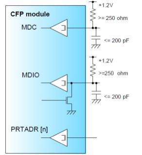
The electrical characteristics of the aforesaid MDIO pins operating in 1.2 V LVCMOS mode.Figure 4-7shows the recommended input and output termination modes of these pins .
1.2 V LVCMOS Electrical Characteristics
|
Parameter |
Symbol |
Min. |
Typ. |
Max. |
Unit |
|
Input high voltage |
VIH |
0.84 |
- |
1.5 |
V |
|
Input low voltage |
VIL |
-0.3 |
- |
0.36 |
V |
|
Input leakage current |
IIN |
-100 |
- |
100 |
μA |
|
Output high voltage (IOH= -100 μA) |
VOH |
1 |
- |
1.5 |
V |
|
Output low voltage (IOL = 100 μA) |
VOL |
-0.3 |
- |
0.2 |
V |
|
Output high current |
IOH |
- |
- |
-4 |
mA |
|
Output low current |
IOL |
+4 |
- |
- |
mA |
|
Input capacitance |
Ci |
- |
- |
10 |
pF |
Mechanical Specifications
The mechanical dimensions of the 100G coherent optical module . Max. dimensions (L × W × H): 107.5 mm × 41 .5 mm × 14.8 mm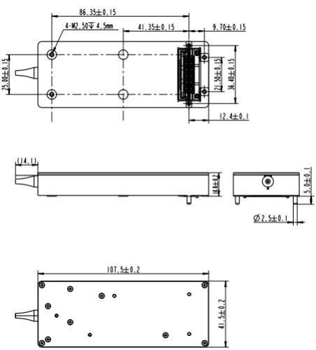
Operating Environment
|
Parameter |
Min. |
Max. |
Unit |
|
Storage temperature |
-40 |
85 |
ºC |
|
Operating case temperature |
0 |
70 |
ºC |
|
Relative humidity, operating(non-condensing) |
5 |
85 |
% |
|
Relative humidity, operating (short term < 96 hrs,non-condensing) |
5 |
95 |
% |
|
ESD sensitivity (HBM) |
High-speed pins: 1000 Other pins: 2000 |
V |
Model
|
Model |
Description |
|
FTC2-2H-DCO-BIDI |
100G Coherent Optical Module |
北亿纤通 | F-tone Networks
企业邮箱: 该邮件地址已受到反垃圾邮件插件保护。要显示它需要在浏览器中启用 JavaScript。
企业手机:19081343401
企业电话:028-85255257
企业传真:028-85977702
注:本产品有全国产化型号可选
本产品为CFP2光模块,仅展示部分参数,如有需要,请联系我们。
Important Notice
Performance figures, data and any illustrative material provided in this data sheet are typical and must be specifically confirmed in writing by F-tone Networks before they become applicable to any particular order or contract. In accordance with the F-tone Networks policy of continuous improvement specifications may change without notice.
The publication of information in this data sheet does not imply freedom from patent or other protective rights of F-tone Networks or others. Further details are available from any F-tone Networks sales representative.