Description
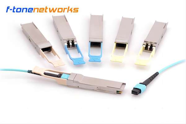
The F-tone Networks 100G QSFP28 SR4 (FTQ2-HG-SR4-M2-xxx) is designed for use in 100-Gigabit Ethernet links up to 100m over Multi-Mode Fiber (MMF) especially for liquid immersion environment. It is compliant with the QSFP28 MSA and IEEE 802.3bm 100GBASE-SR4 and CAUI-4. Digital diagnostics functions are available via the I2C interface, as specified by the QSFP28 MSA. It integrates 4 data lanes in each direction with 4×25.78125Gb/s bandwidth. The electrical interface uses a 38-contact edge type connector. The optical interface uses a single male MPO-12 pigtail. This module incorporates F-tone Networks proven circuit and VCSEL technology to provide reliable long life, high performance, and consistent service.
Features
● Hot-pluggable QSFP28 form factor
● 4 channels full-duplex transceiver module
● Supports 103.125Gb/s aggregate bit rate
● 4 channels 850nm VCSEL array
● 4 channels PIN photo-detector array
● Internal CDR circuits on both receiver and transmitter channels
● Supports CDR bypass
● 2W maximum power dissipation
● Maximum link length of 70m on OM3 MMF and 100m on OM4 MMF
● Single male MPO-12 pigtail
● Single 3.3V power supply
● RoHS compliant (lead free)
● Case operating temperature
Commercial: 0 ~ +60℃
Industrial: -40 ~ +85℃
Applications
● 100GBASE-SR4 100G Ethernet
● Especially design for liquid immersion environment
Absolute Maximum Ratings
|
Parameter |
Symbol |
Min |
Max |
Unit |
|
Supply Voltage |
Vcc |
-0.3 |
3.6 |
V |
|
Input Voltage |
Vin |
-0.3 |
Vcc+0.3 |
V |
|
Storage Temperature |
Ts |
-20 |
85 |
ºC |
|
Case Operating Temperature |
Tc |
0 |
60 |
ºC |
|
Humidity (non-condensing) |
Rh |
5 |
95 |
% |
Recommended Operating Conditions
|
Parameter |
Symbol |
Min |
Typical |
Max |
Unit |
|
Supply Voltage |
Vcc |
3.13 |
3.3 |
3.47 |
V |
|
Operating Case temperature |
Tc |
0 |
60 |
ºC |
|
|
Data Rate Per Lane |
fd |
25.78125 |
Gb/s |
||
|
Humidity |
Rh |
5 |
85 |
% |
|
|
Power Dissipation |
Pm |
2 |
W |
||
|
Fiber Bend Radius |
Rb |
3 |
cm |
||
|
Liquid immersion depth |
10 |
m |
Electrical Specifications
|
Parameter |
Symbol |
Min |
Typical |
Max |
Unit |
|
Differential Input Impedance |
Zin |
90 |
100 |
110 |
ohm |
|
Differential Output Impedance |
Zout |
90 |
100 |
110 |
ohm |
|
Differential Input Voltage Amplitude1 |
ΔVin |
300 |
1100 |
mVp-p |
|
|
Differential Output Voltage Amplitude2 |
ΔVout |
500 |
800 |
mVp-p |
|
|
Skew |
Sw |
300 |
ps |
||
|
Bit Error Rate |
BER |
5×10⁻⁵ |
|||
|
Input Logic Level High |
VIH |
2.0 |
Vcc |
V |
|
|
Input Logic Level Low |
VIL |
0 |
0.8 |
V |
|
|
Output Logic Level High |
VOH |
Vcc-0.5 |
Vcc |
V |
|
|
Output Logic Level Low |
VOL |
0 |
0.4 |
V |
Note:
- Differential input voltage amplitude is measured between TxnP and TxnN.
- Differential output voltage amplitude is measured between RxnP and RxnN.
Optical Characteristics
|
Parameter |
Symbol |
Min |
Typical |
Max |
Unit |
|
Transmitter |
|||||
|
Center Wavelength |
λc |
840 |
850 |
860 |
nm |
|
RMS Spectral Width |
∆λ |
0.6 |
nm |
||
|
Average Launch Power (each lane) |
Pout |
-8.4 |
2.4 |
dBm |
|
|
Optical Modulation Amplitude (each lane) |
OMA |
-6.4 |
3 |
dBm |
|
|
Transmitter and Dispersion Eye Closure (each lane) |
TDEC |
4.3 |
dB |
||
|
Extinction Ratio |
ER |
3 |
dB |
||
|
Average Launch Power of OFF Transmitter (each lane) |
Poff |
-30 |
dB |
||
|
Eye Mask Coordinates1: X1, X2, X3, Y1, Y2, Y3 |
{0.3, 0.38, 0.45, 0.35, 0.41, 0.5} |
||||
|
Receiver |
|||||
|
Center Wavelength |
λc |
840 |
850 |
860 |
nm |
|
Stressed Receiver Sensitivity in OMA2 |
-5.2 |
dBm |
|||
|
Average Power at Receiver Input (each lane) |
-10.3 |
2.4 |
dBm |
||
|
Receiver Reflectance |
RR |
-12 |
dB |
||
|
LOS Assert |
LOSA |
-30 |
dBm |
||
|
LOS De-Assert – OMA |
LOSD |
-7.5 |
dBm |
||
|
LOS Hysteresis |
LOSH |
0.5 |
dB |
||
Note:
- Hit Ratio = 5×10⁻⁵
- Measured with conformance test signal at TP3 for BER=10-5
Mechanical Dimensions
Ordering Information
|
Part Number |
Product Description |
|
FTQ2-HG-SR4-M2-xxx |
QSFP28 SR4, 103.125Gb/s, male MTP pigtail ,liquid immersion,0ºC ~ +60ºC |
|
FTQ2-HG-SR4-M2-xxxI |
QSFP28 SR4, 103.125Gb/s, male MTP pigtail ,liquid immersion,-40ºC ~ +85ºC |


