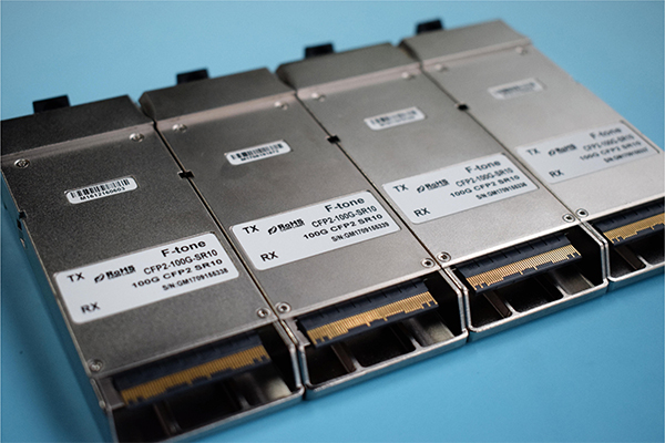
Description
The CFP2 optical transceiver module are a high performance, low power consumption, short reach interconnect solution supporting 100G Ethernet and Telecom. It is compliant with the CFP2 MSA and IEEE P802.3ba 100GBASE-SR10. F-tone Networks CFP2 SR10 modules offer 10 transmit and 10 receive asynchronous channels operating at up to 11.18Gbps per channel.
As shown in Figure 1, the transmitter side of the module consists of an array of VCSELs (Vertical Cavity Surface Emitting Lasers) and associated circuitry, which converts 10 parallel electrical data inputs to 10 parallel optical data output signals and also converts 10 parallel optical signals into 10 parallel electrical signals through an array of PIN photodiodes and associated circuitry. The refclk clock of 161.1328M for 100GE(or 174.6875M for OTU4) is necessary for our module.
Features
● Compliant to CFP2Hardware Specification Version 1.0
● Compliant to CFP2 MSA Management Interface Specification Version 2.2
● Compliant to the IEEE 802.3ba(100GBASE-SR10)
● Transmission data rate up to 11.18Gbit/s per channel
● Up to 300m on OM3 and 400m on OM4 MMF
● Power class 3(<8W max)
● OTU4 compatible
● 10 channels 850nm VCSEL array transmitter
● 10 channels PIN photo detector array receiver
● MDIO digital diagnostic interface(Optional) and control capabilities.
● TX input and RX output CDR retiming
● Hot pluggable electrical interface
● Single 3.3V power supply
● RoHS 6 compliant(lead free)
● Utilizes a standard 24/20 lane optical fiber with MPO connector
● Case operating temperature
Commercial: 0 ~ +70℃
Industrial: -40 ~ +85℃
Applications
● 100GBE interconnects
● High-speed core router connections & Datacom /Telecom switch
● Data aggregation and backplane applications
● Proprietary protocol and density application
Absolute Maximum Ratings
|
Parameter |
Symbol |
Min |
Max |
Unit |
|
Supply Voltage |
Vcc |
-0.5 |
3.6 |
V |
|
Input Voltage |
Vin |
-0.3 |
Vcc+0.3 |
V |
|
Storage Temperature |
Tst |
-40 |
85 |
ºC |
|
Humidity(non-condensing) |
Rh |
5 |
85 |
% |
*Exceeding any one of these values may destroy the device immediately
Recommended Operating Conditions
|
Parameter |
Symbol |
Min |
Typical |
Max |
Unit |
|
Supply Voltage |
Vcc |
3.13 |
3.3 |
3.47 |
V |
|
Operating Case temperature |
Tca |
0 |
70 |
ºC |
|
|
Data Rate Per Lane |
fd |
- |
10.3125 |
11.18 |
Gbps |
|
Power Dissipation |
Pm |
8 |
W |
||
|
Low Power Mode Dissipation |
Plow |
2 |
W |
||
|
Aggregate Bit Rate |
BRaggr |
103.125 |
111.8 |
Gbps |
Electrical Characteristics
|
Parameter |
Symbol |
Min |
Typical |
Max |
Unit |
Notes |
|
Differential input impedance |
Zin |
90 |
100 |
110 |
ohm |
|
|
Differential Output impedance |
Zout |
90 |
100 |
110 |
ohm |
|
|
Differential input voltage amplitude |
ΔVin |
120 |
820 |
mVp-p |
||
|
Differential output voltage amplitude |
ΔVout |
300 |
820 |
mVp-p |
||
|
Input Logic Level High |
VIH |
2.0 |
VCC+0.3 |
V |
3.3V LVCOMS |
|
|
0.84 |
1.2 |
V |
1.2V LVCOMS |
|||
|
Input Logic Level Low |
VIL |
-0.3 |
0.8 |
V |
3.3V LVCOMS |
|
|
-0.3 |
0.36 |
V |
1.2V LVCOMS |
|||
|
Output Logic Level High |
VOH |
VCC-0.2 |
VCC |
V |
3.3V LVCOMS |
|
|
1.0 |
1.5 |
V |
1.2V LVCOMS |
|||
|
Output Logic Level Low |
VOL |
0 |
0.2 |
V |
3.3V LVCOMS |
|
|
-0.3 |
0.2 |
V |
1.2V LVCOMS |
Note:
1. Differential input voltage amplitude is measured between TxnP and TxnN.
2. Differential output voltage amplitude is measured between RxnP and RxnN.
Optical Characteristics
Transmitter Optical Specifications (T = 25°C, VCC =3.3V +/- 5%)
|
Parameter |
Symbol |
Min |
Typical |
Max |
Unit |
|
Average Optical Power(per channel) |
Pout |
-7.6 |
-1 |
+2.4 |
dBm |
|
Average Optical Power(per channel) - Disabled |
Poff |
-30 |
dBm |
||
|
Optical Return Loss Tolerance |
12 |
dB |
|||
|
Extinction Ratio |
ER |
3 |
dB |
||
|
Center Wavelength |
λc |
840 |
850 |
860 |
nm |
|
RMS Spectral Width |
λ |
0.5 |
0.65 |
nm |
|
|
Transmit OMA,per Lane |
TX_OMA/lane |
-5.6 |
3 |
dBm |
|
|
Difference in launch power between any two lanes(OMA) |
4 |
dB |
|||
|
Transmitter and dispersion penalty,each lane |
TDP/lane |
3.5 |
dB |
||
|
Transmitter eye mask |
Compliant to IEEE802.3ba eye mask specification |
||||
Note: Average optical power is measured at the output of the modules optical interface.
Receiver Optical Specifications (T = 25°C, VCC =3.3V +/- 5%)
|
Parameter |
Symbol |
Min |
Typical |
Max |
Unit |
|
Optical Power Sensitivity(per channel) |
Pin min |
- |
-12 |
-9.9 |
dBm |
|
Optical Power Saturation(per channel) |
Pin max |
+1 |
- |
- |
dBm |
|
Stressed Receiver Sensitivity |
PS |
- |
- |
-5.4 |
dBm |
|
Center Wavelength |
λc |
840 |
850 |
860 |
nm |
|
RMS Spectral Width |
λ |
0.5 |
0.65 |
nm |
|
|
Optical Return Loss |
Rl |
12 |
dB |
||
|
Damage Threshold |
3.4 |
dBm |
|||
|
Optical modulation amplitude,each lane |
3 |
dBm |
Note:Optical power sensitivity is measured with BER@10-12at 10.3125Gbps per channel.
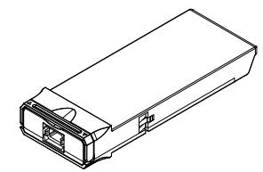
Mechanical Dimensions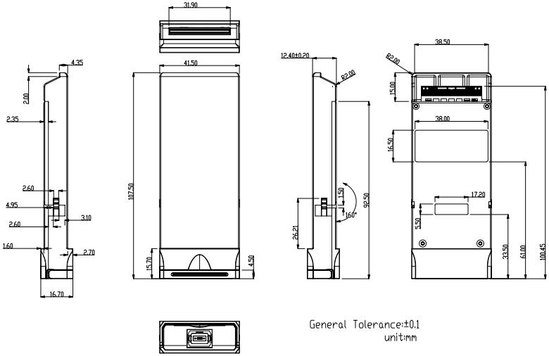
Ordering Information
|
Part Number |
Product Description |
|
FTC2-HG-SR10 |
CFP2,100GBASE-SR10, 300m on OM3 MMFand400m on OM4 MMF,0ºC ~ +70ºC |
|
FTC2-HG-SR10I |
CFP2,100GBASE-SR10, 300m on OM3 MMFand400m on OM4 MMF,-40ºC ~ +85ºC |
北亿纤通 | F-tone Networks
企业邮箱: 该邮件地址已受到反垃圾邮件插件保护。要显示它需要在浏览器中启用 JavaScript。
企业手机:19081343401
企业电话:028-85255257
企业传真:028-85977702
注:本产品有全国产化型号可选
本产品为CFP2光模块,仅展示部分参数,如有需要,请联系我们。
Important Notice
Performance figures, data and any illustrative material provided in this data sheet are typical and must be specifically confirmed in writing by F-tone Networks before they become applicable to any particular order or contract. In accordance with the F-tone Networks policy of continuous improvement specifications may change without notice.
The publication of information in this data sheet does not imply freedom from patent or other protective rights of F-tone Networks or others. Further details are available from any F-tone Networks sales representative.