Description
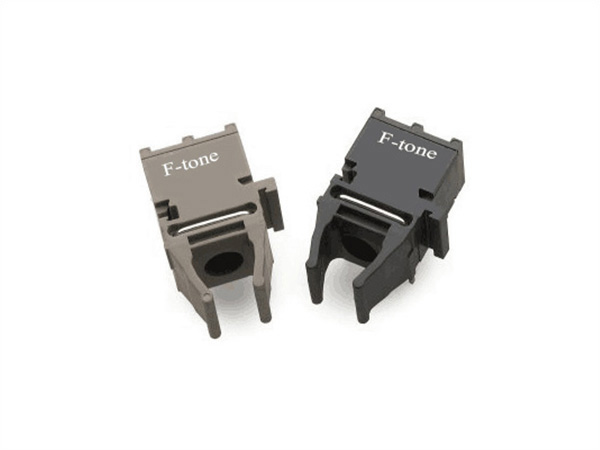
The F-tone Networks CFP4 100GEBASE-LR4 optical transceiver is a hot pluggable 100Gbps small-form-factor transceiver module. It is designed for use in 100 Gigabit Ethernet links and 4x28G OTN client interfaces over single mode fiber. It is compliant with the CFP MSA, IEEE 802.3ba 100GBASE LR4 and OTU4 4I1-9D1F. The module converts 4 input channels of 25Gb/s electrical data to 4 channels of LAN WDM optical signals and then multiplexes them into a single channel for 100Gb/s optical transmission. On the receiver side, the module de-multiplexes the 100Gb/s optical into 4 channels of LAN WDM optical signals and then converts them to 4 output channels of electrical data. The module is a multi-rate optical transceiver which data rate up to 28Gbps per channel. The high performance cooled LAN WDM EML Integrated TOSA and PIN-base Integrated ROSA provide superior performance for Telecom and Datacom applications up to 10km links.
Features
● 4 channels full-duplex transceiver modules
● Transmission data rate up to 28Gbps per channel
● 4 X 25/28G LAN-WDM EML Integrated TOSA Cooling transmitter
● 4 channels PIN-base Integrated ROSA
● Compliant with CFP4 MSA hardware specification
● Compliant with CFP MSA management specification
● Compliant to IEEE 802.3ba specification for 100GBASE-LR4
● Compliant to OTU4
● Transmission distance up to 10km on SMF
● 4 parallel electrical serial interface and AC coupling of CML signals
● MDIO real-time digital diagnostic and control capabilities
● Internal CDR circuits on both receiver and transmitter channels
● Hot pluggable
● Total Power Consumption<4W
● 3.3V power supply
● Duplex LC receptacle optical interface
● RoHS 6 compliant(lead free)
● Case operating temperature
Commercial: 0 ~ +70℃
Industrial: -40 ~ +85℃
Applications
● 100GbE IEEE 802.3ba 100GBASE-LR4
● ITU-T G.959.1 OTU4 (4I1-9D1F)
● Switch to switch interface or Switch to router interface
Absolute Maximum Ratings
|
Parameter |
Symbol |
Unit |
Min |
Max |
|
Supply Voltage |
VCC |
V |
-0.5 |
3.6 |
|
Storage Temperature |
Ts |
°C |
-40 |
85 |
|
Operating Case Temperature |
Tc |
°C |
0 |
70 |
|
Relative Humidity (Non condensation) |
- |
% |
5 |
85 |
Recommended Operating Conditions
|
Parameter |
Symbol |
Unit |
Min |
Typ |
Max |
|
Operating Case Temperature |
Tc |
°C |
0 |
- |
70 |
|
Supply Voltage |
VCC |
V |
3.13 |
3.3 |
3.47 |
|
Supply Current |
ICC |
A |
- |
- |
1.27 |
|
Power Dissipation |
- |
W |
- |
- |
4 |
Optical Characteristics(Tested under recommended operating conditions, unless otherwise noted)
|
Parameter |
Symbol |
Unit |
Value |
Notes |
||
|
Min |
Typ |
Max |
||||
|
Optical Transmitter Characteristics |
||||||
|
Signaling Rate for Each Lane (100GbE) |
- |
Gbps |
25.78125 |
|||
|
Signaling Rate for Each Lane (OTU4) |
27.9525 |
|||||
|
Four lane Wavelength Range |
入1 |
nm |
1294.53 |
1295.56 |
1296.59 |
|
|
入2 |
1299.02 |
1300.05 |
1301.09 |
|||
|
入3 |
1303.54 |
1304.58 |
1305.63 |
|||
|
入4 |
1308.09 |
1309.14 |
1310.19 |
|||
|
Side Mode Suppression Ratio |
SMSR |
dB |
30 |
|||
|
Total Average Launch |
dBm |
10.5 |
||||
|
Average Launch Power for Each Lane(100GbE) |
Pa |
dBm |
-4.3 |
+4.5 |
||
|
Average Launch Power for Each Lane(OTU4) |
-2.5 |
+2.9 |
||||
|
Difference in launch power between any two lanes (Average and OMA) |
dB |
5 |
||||
|
Extinction Ratio |
ER |
dB |
7 |
|||
|
Average Launch Power OFF |
Poff |
dBm |
-30 |
|||
|
Optical Return Loss Tolerance |
dB |
20 |
||||
|
Optical Receiver Characteristics |
||||||
|
Receiver Sensitivity in OMA for Each Lane(100GbE) |
Pmin |
dBm |
- |
- |
-8.6 |
1 |
|
Equivalent Sensitivity for Each Lane(OTU4) |
-10.3 |
2 |
||||
|
Los Assert |
dBm |
-20 |
||||
|
Los De-assert |
dBm |
-12 |
||||
|
Los Hysteresis |
dBm |
0.5 |
||||
|
Damage Threshold, each Lane |
THd |
dBm |
5.5 |
3 |
||
|
Receive Power In OMA for Each Lane |
PinOMA |
dBm |
4.5 |
|||
|
Difference in Receive Power between any Two Lanes (Average and OMA) |
Prx,diff |
dB |
4.5 |
|||
|
Average Receive Power for Each Lane(100GbE) |
Pin |
dBm |
-10.6 |
4.5 |
||
|
Average Receive Power for Each Lane(OTU4) |
-8.8 |
2.9 |
||||
Note:
1. Minimum average optical power measured at BER less than 1E-12, with a 231-1 PRBS.
2. Measured with PRBS 231-1 for BER=10-6. The BER for the OTU4 application is required to be met only after FEC has been applied.
3. The receiver shall be able to tolerate, without damage, continuous exposure to a modulated optical input signal having this power level on one lane. The receiver does not have to operate correctly at this input power.
Electrical Characteristics(Tested under recommended operating conditions, unless otherwise noted)
|
Parameter |
Symbol |
Unit |
Min |
Typ |
Max |
Note |
|
Differential Data Output Swing |
Vout,pp |
mV |
300 |
- |
850 |
|
|
Differential Input Voltage Swing |
Vin,pp |
mV |
900 |
|||
|
Differential Signal Output Resistance |
Ω |
90 |
- |
110 |
||
|
Differential Signal Input Resistance |
Ω |
90 |
- |
110 |
Low Speed Electrical Interface
|
Parameter |
Symbol |
Unit |
Min |
Max |
Note |
|
Input Voltage |
VIH |
V |
2.0 |
Vcc3 + 0.3 |
1 |
|
VIL |
V |
-0.3 |
0.8 |
||
|
Output Voltage |
VOH |
V |
Vdd3-0.5 |
Vdd3 + 0.3 |
|
|
VOL |
V |
0.0 |
0.4 |
||
|
Input Leakage Current |
3.3VIL |
uA |
-10 |
10 |
|
|
Minimum Pulse Width of Control Pin Signal |
T_CNTL |
us |
100 |
|
|
|
1.2V LVCMOS Electrical Characteristics |
|||||
|
Input High Voltage |
1.2VIH |
V |
0.84 |
1.5 |
|
|
Input Low Voltage |
1.2VIL |
V |
-0.3 |
0.36 |
|
|
Input Leakage Current |
1.2IIN |
uA |
-100 |
+ 100 |
|
|
Output High Voltage |
1.2V0H |
V |
1.0 |
1.5 |
|
|
Output Low Voltage |
1.2V0L |
V |
-0.3 |
0.2 |
|
|
Output High Current |
1.2I0H |
mA |
-4 |
|
|
|
Output Low Current |
1.2I0L |
mA |
+4 |
|
|
|
Input Capacitance |
Ci |
pF |
10 |
|
|
Note1: Vdd3 is host +3.3V power supply.
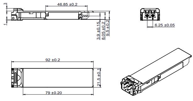
Mechanical Dimensions
Ordering Information
|
Part Number |
Product Description |
|
FTC4-HG-LR4 |
CFP4, LAN-WDM EML transmitter, PIN ROSA,100GE/OTU4,10km,0ºC ~ +70ºC |
|
FTC4-HG-LR4I |
CFP4, LAN-WDM EML transmitter, PIN ROSA,100GE/OTU4,10km,-40ºC ~ +85ºC |
北亿纤通 | F-tone Networks
企业邮箱: 该邮件地址已受到反垃圾邮件插件保护。要显示它需要在浏览器中启用 JavaScript。
企业手机:19081343401
企业电话:028-85255257
企业传真:028-85977702
注:本产品有全国产化型号可选
本产品为CFP4光模块,仅展示部分参数,如有需要,请联系我们。
Important Notice
Performance figures, data and any illustrative material provided in this data sheet are typical and must be specifically confirmed in writing by F-tone Networks before they become applicable to any particular order or contract. In accordance with the F-tone Networks policy of continuous improvement specifications may change without notice.
The publication of information in this data sheet does not imply freedom from patent or other protective rights of F-tone Networks or others. Further details are available from any F-tone Networks sales representative.