Description
The F-tone Networks’s100Gb/s transceiver module for optical communication applications compliant to 100GBASE-SR4 of the IEEE P802.3bm standard. The module converts 4 input channels of 25Gb/s electrical data to 4 channels of VCSEL optical signals over 4 multimode fibers for 100Gb/s optical transmission. Reversely, on the receiver side, the module receives 4 channels of VCSEL optical signals over 4 multimode fibers and then converts them to 4 output channels of electrical data.
The high speed VCSEL transmitters and high sensitivity PIN receivers provide superior performance for 100Gigabit Ethernet applications up to 100m links over OM4 multimode fibers and compliant to optical interface with IEEE802.3bm Clause 95 100GBASE-SR4 requirements.
This product contains an MTP/MPO optical connector for the optical interface and a 56-pin connector for the electrical interface. Figure 1 shows the functional block diagram of this product.
The CFP4 module supports the MDIO interface specified in IEEE802.3bm Clause 45. It supportsalarm, control and monitor functions via hardware pins and via an MDIO bus. Upon module initialization, these functions are available. CFP4 MDIO electrical interface consists of 6 wires including 2 wires of MDC and MDIO, as well as 3 Port Address wires, and the Global Alarm wire. The CFP4 uses pins in the electrical connector to instantiate the MDIO interface as listed in Table 1. MDIO Interface Pins.
Features
● Hot pluggable CFP4 MSA form factor
● Supports 103.1Gb/s to 112.2Gb/s aggregate bit rates
● Compliant to IEEE 802.3bm 100GBASE-SR4
● Power class 2 (<2.5W max)
● Up to70m on OM3 and 100m OM4 MMF transmission
● Up to 28Gb/s data rate per channel
● 4x28G Electrical Serial Interface (CEI-28G-VSR)
● MDIO management interface with digital diagnostic monitoring (Optional)
● Maximum power consumption <2.5W
● Utilizes a standard 12/8 lane optical fiber with MPO connector
● RoHS 6 compliant(lead free)
● 4×28Gb/s 850mm VCSEL-based transmitter
● Case operating temperature
● Commercial: 0 ~ +70℃
● Industrial: -40 ~ +85℃
Applications
● 100GBASE-SR4 Ethernet
● OTN OTU4
● 128G Fiber Channel
Absolute Maximum Ratings
|
Parameter |
Symbol |
Min |
Max |
Unit |
Notes |
|
Storage Temperature |
Ts |
-40 |
85 |
degC |
|
|
Relative Humidity (non-condensation) |
RH |
85 |
% |
||
|
Operating Case Temperature |
TOP |
0 |
70 |
degC |
|
|
Supply Voltage |
Vcc |
-0.5 |
3.6 |
V |
|
|
Voltage on LVTTL Input |
Vilvttl |
-0.5 |
VCC3+0.3 |
V |
|
|
LVTTL Output Current |
Iolvttl |
15 |
mA |
||
|
Voltage on Open Collector Output |
Voco |
0 |
6 |
V |
|
|
Damage Threshold, each Lane |
THd |
3.4 |
dBm |
1 |
Notes:PIN receiver.
Recommended Operating Conditions and Supply Requirements
|
Parameter |
Symbol |
Min |
Typical |
Max |
Unit |
Notes |
|
Operating Case Temperature |
TOP |
0 |
70 |
degC |
||
|
Power Supply Voltage |
VCC |
3.135 |
3.3 |
3.465 |
V |
|
|
Data Rate, each Lane |
25.78125 |
Gbps |
1 |
|||
|
Data Rate, each Lane |
27.9525 |
Gbps |
2 |
|||
|
Control Input Voltage High |
2 |
Vcc |
V |
|||
|
Control Input Voltage Low |
0 |
0.8 |
V |
|||
|
Power Supply Noise |
Vrip |
2 |
% |
DC-1MHz |
||
|
3 |
% |
1-10MHz |
||||
|
Link Distance (OM3 MMF) |
D1 |
70 |
m |
|||
|
Link Distance (OM4 MMF) |
D2 |
100 |
m |
Notes:
1.100GBASE-SR4.
2.OUT4 with FEC.
Electrical Characteristics
|
Parameter |
Symbol |
Min |
Typical |
Max |
Unit |
Notes |
|
Power Consumption |
2.5 |
W |
||||
|
Supply Current |
Icc |
800 |
mA |
|||
|
Low Power Mode Power Dissipation |
1 |
W |
||||
|
Transmitter (each Lane) |
||||||
|
Single-ended Input Voltage Tolerance (Note 1) |
-0.3 |
4.0 |
V |
Referred to TP1 signal common |
||
|
AC Common Mode Input Voltage Tolerance |
15 |
mV |
RMS |
|||
|
Differential Input Voltage Swing Threshold |
50 |
mVpp |
LOSA Threshold |
|||
|
Differential Input Voltage Swing |
Vin,pp |
190 |
700 |
mVpp |
||
|
Differential Input Impedance |
Zin |
90 |
100 |
110 |
Ohm |
|
|
Receiver (each Lane) |
||||||
|
Single-ended Output Voltage |
-0.3 |
4.0 |
V |
Referred to signal common |
||
|
AC Common Mode Output Voltage |
7.5 |
mV |
RMS |
|||
|
Differential Output Voltage Swing |
Vout,pp |
300 |
850 |
mVpp |
||
|
Differential Output Impedance |
Zout |
90 |
100 |
110 |
Ohm |
|
|
Termination Mismatch at 1MHz |
5 |
% |
||||
Notes:The single ended input voltage tolerance is the allowable range of the instantaneous input signals.
Optical Characteristics
|
Parameter |
Symbol |
Min |
Typical |
Max |
Units |
Notes |
|
Transmitter |
||||||
|
Center Wavelength |
λC |
840 |
850 |
860 |
nm |
|
|
RMS Spectral Width |
∆λrms |
0.6 |
nm |
|||
|
Average Launch Power, each Lane |
PAVG |
-8.4 |
2.4 |
dBm |
||
|
Optical Modulation Amplitude (OMA), each Lane |
POMA |
-6.4 |
3.0 |
dBm |
1 |
|
|
Difference in Launch Power between any Two Lanes (OMA) |
Ptx,diff |
4.0 |
dB |
|||
|
Launch Power in OMA minus TDEC, each Lane |
-7.3 |
dBm |
||||
|
Transmitter and Dispersion Eye Closure (TDEC), each Lane |
4.3 |
dB |
||||
|
Extinction Ratio |
ER |
2.0 |
dB |
|||
|
Optical Return Loss Tolerance |
TOL |
12 |
dB |
|||
|
Encircled Flux |
≥86% at 19um ≤ 30% at 4.5um |
|||||
|
Transmitter Eye Mask Definition {X1, X2, X3, Y1, Y2, Y3}, 5×10⁻⁵ hits/sample |
{0.3,0.38,0.45,0.35,0.41,0.5} |
2 |
||||
|
Average Launch Power OFF Transmitter, each Lane |
Poff |
-30 |
dBm |
|||
|
Receiver |
||||||
|
Center Wavelength |
λC |
840 |
850 |
860 |
nm |
|
|
Damage Threshold, each Lane |
THd |
3.4 |
dBm |
3 |
||
|
Average Receive Power, each Lane |
-10.3 |
2.4 |
dBm |
|||
|
Receiver Reflectance |
RR |
-12 |
dB |
|||
|
Receive Power (OMA), each Lane |
3.0 |
dBm |
||||
|
Stressed Receiver Sensitivity (OMA), each Lane |
-5.2 |
dBm |
4 |
|||
|
LOS Assert |
LOSA |
-30 |
dBm |
|||
|
LOS Deassert |
LOSD |
-12 |
dBm |
|||
|
LOS Hysteresis |
LOSH |
0.5 |
2 |
dB |
||
|
Conditions of Stress Receiver Sensitivity Test (Note 5): |
||||||
|
Stressed Eye Closure (SEC), Lane under Test |
4.3 |
dB |
||||
|
Stressed Eye J2 Jitter, Lane under Test |
0.39 |
UI |
||||
|
Stressed Eye J4 Jitter, Lane under Test |
0.53 |
UI |
||||
|
OMA of each Aggressor Lane |
3 |
dBm |
||||
|
Stressed receiver eye mask definition {X1, X2, X3, Y1, Y2, Y3} |
{0.28,0.5,0.5,0.33,0.33,0.4} |
|||||
Notes:
1.Even if the TDP < 0.9 dB, the OMA min must exceed the minimum valuespecified here.
2.See Figure 5 below.
3.The receiver shall be able to tolerate, without damage, continuous exposure to a modulated optical input signal having this power level on one lane. The receiver does not have to operate correctly at this input power.
4.Measured with conformance test signal at receiver inputfor BER = 1x10-12.
5.Stressed eye closure and stressed eye jitter are test conditions for measuring stressed receiver sensitivity. They are not characteristics of the receiver.
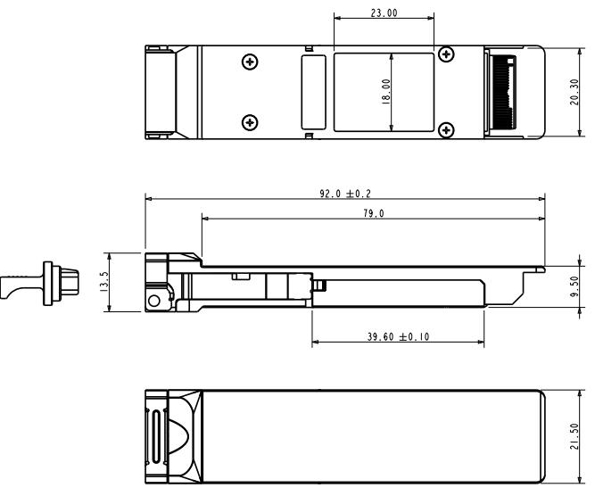
Mechanical Dimensions
Ordering Information
|
FTC4-HG-SR4 |
CFP4-SR4 100m optical transceiver with full real-time digital diagnostic monitoring and pull tab,0ºC ~ +70ºC |
|
FTC4-HG-SR4I |
CFP4-SR4 100m optical transceiver with full real-time digital diagnostic monitoring and pull tab,-40ºC ~ +85ºC |
北亿纤通 | F-tone Networks
企业邮箱: 该邮件地址已受到反垃圾邮件插件保护。要显示它需要在浏览器中启用 JavaScript。
企业手机:19081343401
企业电话:028-85255257
企业传真:028-85977702
注:本产品有全国产化型号可选
本产品为CFP4光模块,仅展示部分参数,如有需要,请联系我们。
Important Notice
Performance figures, data and any illustrative material provided in this data sheet are typical and must be specifically confirmed in writing by F-tone Networks before they become applicable to any particular order or contract. In accordance with the F-tone Networks policy of continuous improvement specifications may change without notice.
The publication of information in this data sheet does not imply freedom from patent or other protective rights of F-tone Networks or others. Further details are available from any F-tone Networks sales representative.